
Rebar Coupler Prep Bottlenecks on Site: A Problem-Solution Guide to Threading 16–40 mm Bars
A rebar coupler is rarely the reason a connection stops. The stop usually happens upstream, at the bar end — where the wrong diameter was matched to the wrong coupler family, where the thread did not hold its 60° flank angle, or where the threading machine could not keep pace with the deck. This guide diagnoses that bottleneck and fixes it in the order the site experiences it: diameter match, thread geometry, then threading equipment.
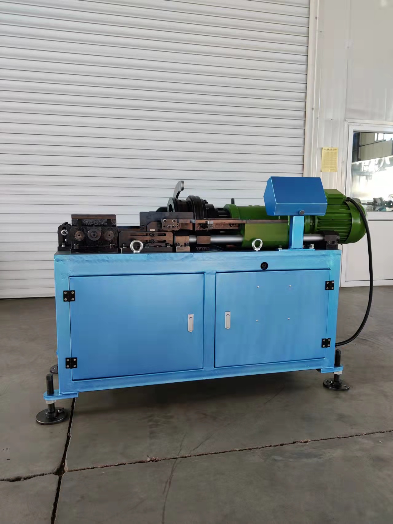
Most site teams measure coupler performance in the wrong place. They count couplers delivered, they count connections signed off, and they look for the fault in the connector. The queue, however, forms between the cut-off saw and the wrench. Rebar couplers are designed to be a fast mechanical splice; the speed advantage only materialises when a prepared bar end is available at the moment the crew needs it.
Three preparation variables decide whether that happens on a 16 mm column cage or a 40 mm bridge segment: the material and type match for the bar diameter, the thread geometry carried on the bar end, and the throughput and thread-length envelope of the threading machine. Diagnosis has to follow that same order, because a fix applied out of sequence produces a site that threads faster but still rejects at trial-fit.
What Counts as a Prep Bottleneck
A prep bottleneck is any point between bar cutting and coupler wrenching where bar ends are not available in the required quantity, diameter, thread specification and thread length for the connection sequence that follows. It is a workflow condition, not a product defect, and it shows up in six recognisable symptoms:
- Bars pass inspection but are rejected at trial-fit against the coupler.
- Threads engage at the coupler mouth but the two bar ends do not reach the middle of the coupler.
- Operators re-cut or re-thread ends that already passed the threading station.
- The threading machine sits idle while crews change setup for a different diameter.
- Wrenching time per connection rises without any change in coupler supply.
- Fitters wait at the connection point while prepared bars wait somewhere else on site.
The distinction matters commercially. A coupler defect is a supplier conversation; a prep defect is a site conversation about cycle time, re-work and idle labour. On projects where the connection count runs into the thousands, the second conversation costs more.
Why Preparation Now Sets the Programme
Mechanical splicing has moved from a specialist alternative to a mainstream method, and the volumes reflect it. The global rebar coupler market was valued at USD 1.82 billion in 2025 and is projected to reach USD 3.47 billion by 2034, with Asia Pacific accounting for 41.3% of global revenue in 2025 (Dataintelo, Rebar Coupler Market Research Report 2034). More connections per project means more bar ends per shift, and the preparation step inherits the pressure that used to sit with lap tying and welding crews.
The comparison is well documented at project level. Against traditional on-site lap binding, mechanical couplers are reported to deliver 50%–70% lower cost, easier operation and better quality control, with installation 3–5 times faster than lap tying; because bars are pre-threaded at the factory, on-site installation is 2–4 times faster than welding. Against welding specifically, the connection is not affected by weather conditions, worker cost is around 50% lower, and quality control and installation are easier — which is why the method is preferred for high-rise buildings, cross-sea bridges and airport construction.
Those figures assume something the brochure does not say out loud: that the prepared bar end is ready when the crew is. Every one of those speed and cost advantages is created by moving work off the critical path — factory pre-threading, then a fast field assembly. A bottleneck at the on-site threading station puts the work straight back onto the critical path, and the savings that justified the method disappear first, before any coupler is ever questioned.
The compliance framework has also tightened around the same workflow. ISO 15835-1:2018 specifies requirements for couplers used for mechanical splices of steel reinforcing bars; ISO 15835-2:2018 specifies the test methods applicable to those couplers; ISO 15835-3:2018 specifies rules for certification and self-evaluation. Mechanical splices are commonly specified against ISO 15835 alongside ASTM A615 and BS 8110 / Eurocode 2 requirements. None of these documents inspects a thread angle on site — that remains the contractor's control point, which is exactly where prep discipline is decided. Importers tracking shipments separately should note the standard HS classification for rebar couplers, 7307.92.90.
The Fix in Three Layers
Layer 1 — Match 16–40 mm Bar Diameter to the Right Coupler Family
Diameter alone does not identify a coupler. Two couplers that both fit a 25 mm bar can carry different thread forms and different base materials, and a bar-end thread cut for one will not assemble into the other. On a mixed-diameter site, this is the most common source of trial-fit rejection.
The three families that dominate site work are the rolled (parallel thread) coupler, the pressing coupler and the one-touch quick connection coupler, and each pairs with a specific material route:
- Rolled / parallel thread rebar coupler — carbon steel 45# or alloy steel 40CR. The bar end is threaded by rolling, and the coupler is a parallel-thread sleeve.
- Pressing rebar coupler — carbon steel Q355B, supplied across sizes 16, 18, 20, 22, 25, 28, 32, 36 and 40.
- One-touch / quick connection rebar coupler — alloy steel 40CR, model designation covering 16, 18, 20, 22, 25, 28, 32, 36 and 40.
Material choice is not cosmetic. Cangzhou Bartech Construction Material Co., Ltd., a supplier of rebar couplers and rebar threading machines based in Qing County, Cangzhou, Hebei, China, reports producing couplers from S45C carbon steel with tensile strength above 600 MPa and 40Cr alloy steel at approximately 980 MPa. Where a specification calls for a high-strength, alloy steel or carbon steel coupler, the prep plan has to name the material family at the same time as the diameter — because the threading setup follows the material and thread form, not the bar size alone.
Two adjacent families are worth flagging for sites that have inherited a specification: upset forged couplers, produced through parallel thread upsetting, and cold extrusion couplers, produced through cold pressing technology. Both are offered within the same manufacturing technology range as rolling and pressing. Upsetting changes the prep step entirely — the bar end is deformed before threading, using equipment such as the 50S rebar upsetting machine, which has a net weight of 1200 kg, overall dimensions of 1350 mm × 950 mm × 1750 mm, rated voltage of 380 V / 50 Hz, main motor power of 11 kW, maximum pressure of 31.5 MPa and oil pump flux of 16 ml/r, and processes rebar sizes 16–50 mm for 400 rebar and 16–40 mm for 500 rebar. If the drawing specifies an upset forged coupler, a plain threading machine will not produce a compliant bar end, and no amount of threading speed will clear the queue.
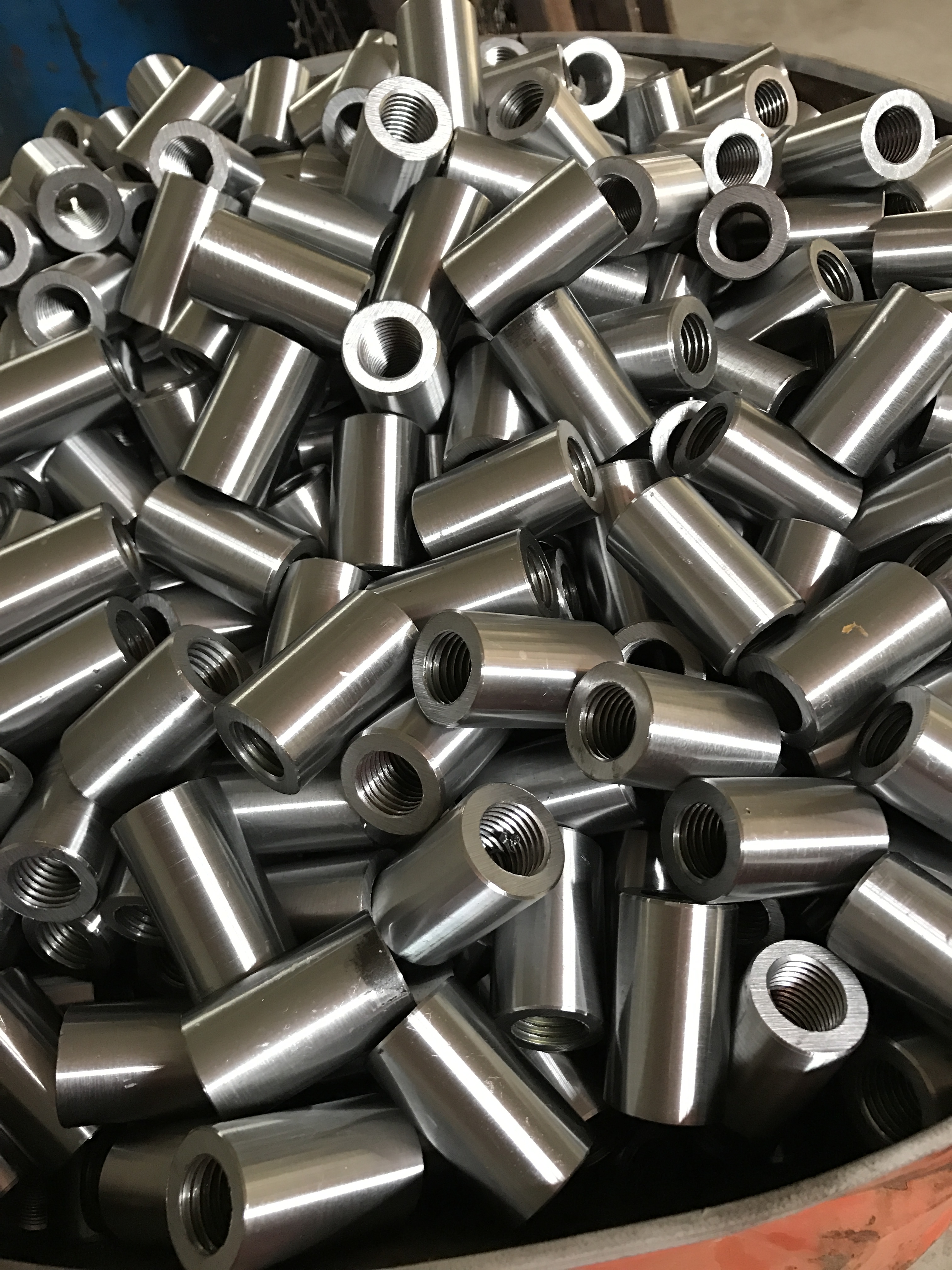
Layer 2 — Lock the Thread Geometry: 60° Flank Angle and Model Thread Specs
Once the family is right, the thread has to be right. Two numbers govern acceptance on most coupler programmes:
- Thread angle: 60°. The flank angle carried on the bar end must match the coupler thread. An angle that drifts produces a thread that appears to engage but carries load on the wrong flank.
- Model thread specification. A 16 mm bar uses the M16.5*2.5 thread; a 32 mm bar uses the M32.6*3.0 thread. The decimal in the designation is not a rounding artefact — it is the thread size the coupler is cut for.
Thread length is the third control, and it is the one that connects prep to the documented field failure. If the bar end is threaded shorter than the coupler requires, the two ends will not meet in the middle of the sleeve when wrenched, and the connection is not properly made. Thread gauges, go/no-go checks and a fixed thread-length setting on the machine are the practical controls; visual inspection at the coupler mouth is not.
Dimensional verification closes this layer. Couplers are supplied to a defined outside diameter, overall length and wall thickness per bar size, and the prepared assembly should be checked against those values rather than against a sample coupler from another batch:
| Bar size | Coupler outer diameter | Coupler length | Wall thickness |
|---|---|---|---|
| φ16 | 30 mm | 110 mm | 4.5 mm |
| φ18 | 34 mm | 120 mm | 5.4 mm |
| φ20 | 36 mm | 120 mm | 5.5 mm |
| φ22 | 40 mm | 132 mm | 6.4 mm |
| φ25 | 45 mm | 150 mm | 7.4 mm |
| φ28 | 50 mm | 168 mm | 8.0 mm |
| φ32 | 56 mm | 192 mm | 9.0 mm |
| φ36 | 63.2 mm | 220 mm | 11.3 mm |
| φ40 | 70 mm | 240 mm | 11.0 mm |
These dimensions also explain a frequent misdiagnosis. A 40 mm coupler at 70 mm outer diameter and 240 mm length needs substantially more thread engagement and more wrench travel than a 16 mm coupler at 30 mm and 110 mm. Crews that keep one wrenching rhythm across the full range will report "slow couplers" on the large-diameter pours when the real constraint is preparation and assembly time per size.
Layer 3 — Choose Threading Equipment That Matches the Actual Throughput
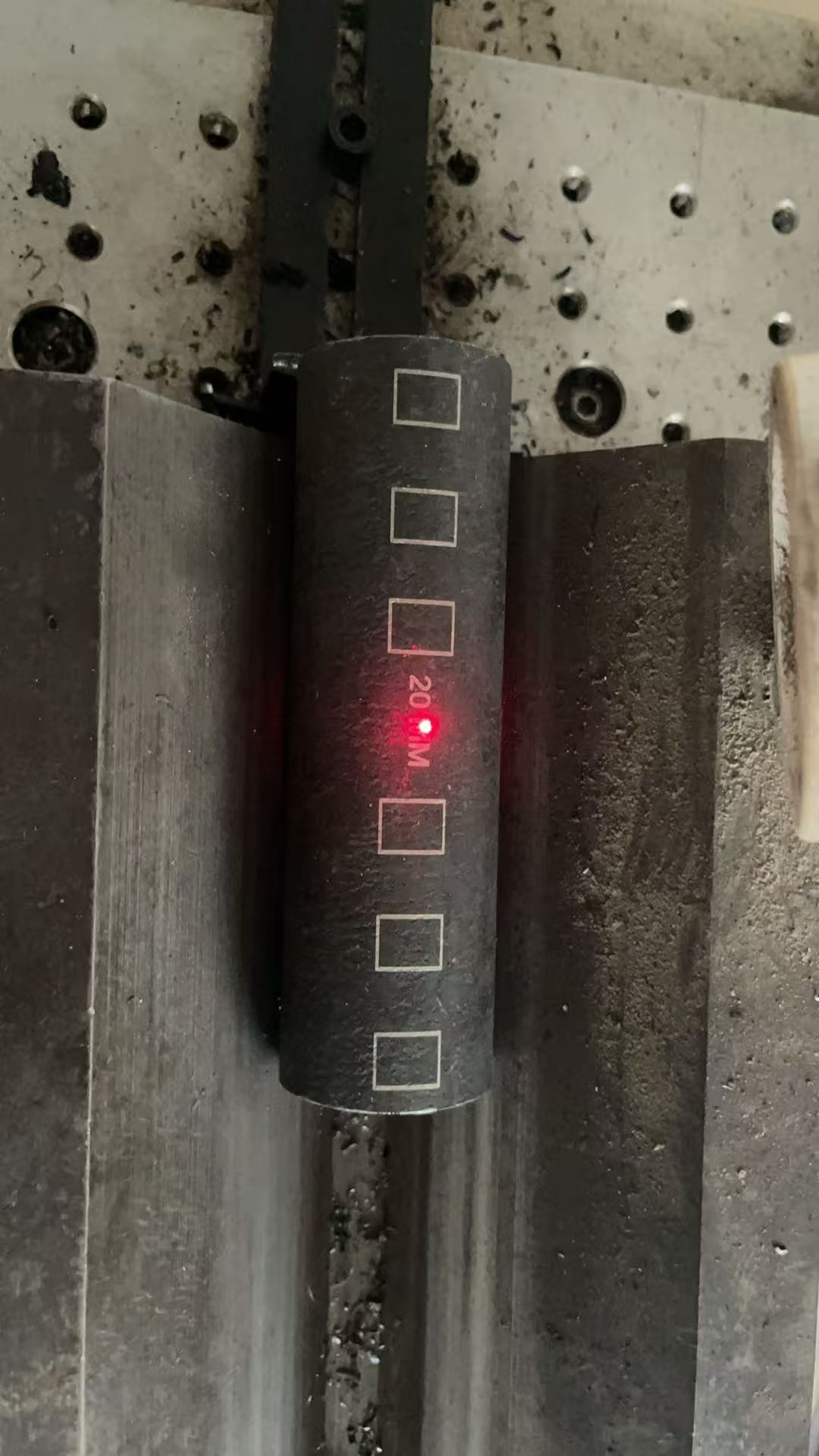
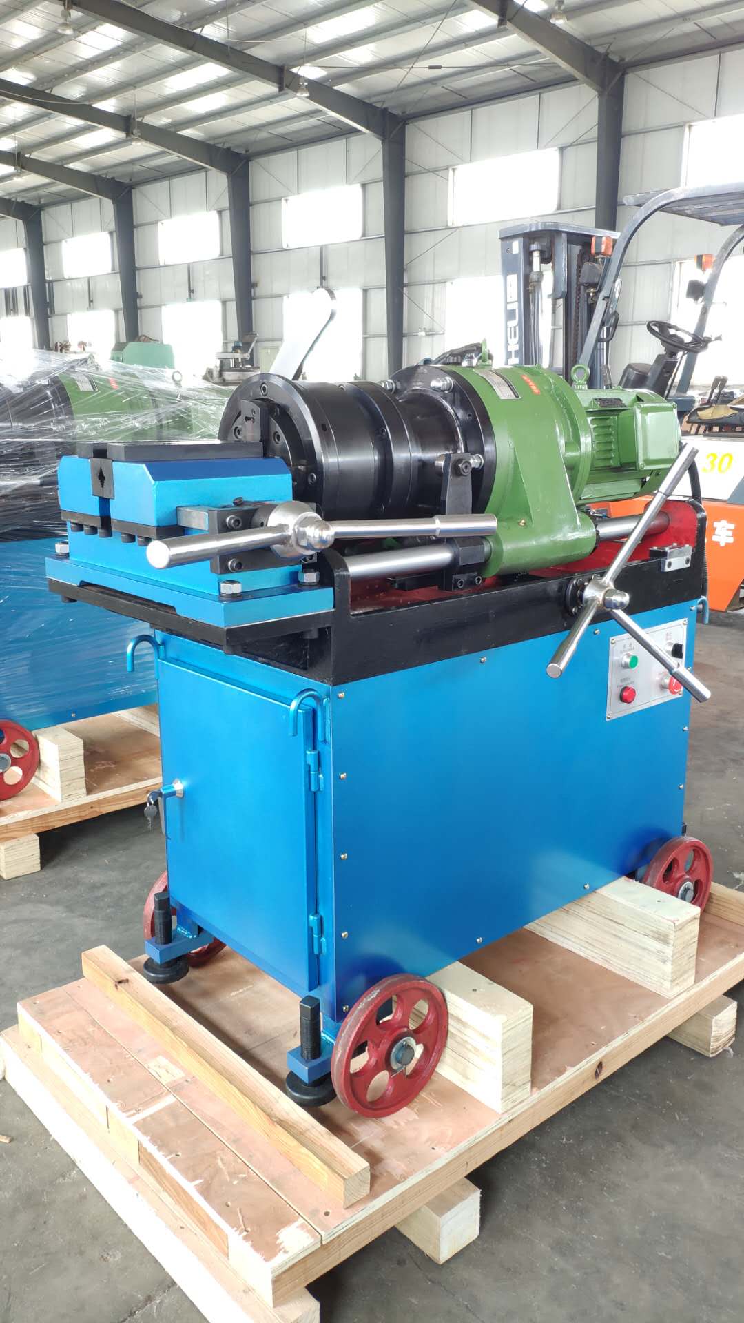
The third layer is the machine. Two models cover the standard site requirement, with a third for automated output:
- CBT40A / CBT40L rebar threading machine — 5.5 kW, 380 V / 50 Hz, with a 1:23 quick speed and a 1:29 slow speed, and a maximum threading length of 95 mm.
- 40AO automatic threading machine — the automated option, specified where output rather than operator pace sets the rate.
The two speed settings are the practical lever on a mixed-diameter deck. The 1:23 quick mode favours the high-count, smaller-diameter work that dominates column and wall cages; the 1:29 slow mode suits the heavier ends where thread quality on larger bars matters more than cycle time. Running everything in one mode is a common cause of a queue that appears on one pour and not the next.
The 95 mm maximum threading length is the second lever, and it must be reconciled with the coupler dimension before production starts. A thread shorter than the coupler requirement will not reach the middle of the sleeve; a thread planned without reference to the machine envelope creates a second operation. The dimensional table above is the reference for making that reconciliation once, rather than pour by pour.
Step-by-Step: Clearing a Prep Bottleneck in Six Moves
Step 1 — Locate the queue before changing any setting
Walk the flow from cut-off saw to wrench and record where bars physically wait. A queue in front of the threading machine points to machine capacity or mode selection; a queue in front of the wrench points to thread length or diameter mismatch. The two have different fixes, and applying the wrong one adds cost without removing the delay.
Step 2 — Fix the diameter-to-family map for 16–40 mm
Publish a single sheet listing, for each bar size from 16 to 40 mm, which coupler family applies (rolled / parallel thread in carbon steel 45# or alloy 40CR, pressing in Q355B, one-touch in 40CR) and which thread specification follows. Every trial-fit rejection traced to a mismatch disappears once this map is fixed at the drawing stage rather than at the coupler.
Step 3 — Verify the thread against 60° and the model specification
Confirm the 60° flank angle and the model thread — M16.5*2.5 at 16 mm, M32.6*3.0 at 32 mm — with gauges at the machine, not downstream. Record the check per shift so that a drifting die or roller is caught before a pour, not after a rejection.
Step 4 — Set thread length against the 95 mm machine envelope and the coupler dimension
Align the threading length setting with the coupler length for that bar size, keeping within the 95 mm maximum threading length of the CBT40A / CBT40L. This is the step that makes mid-coupler engagement achievable at the wrench, and it is the control the documented failure mode calls for.
Step 5 — Assemble with a wrench that seats both ends in the middle
Use the rebar coupler electrical wrench to drive both bar ends until they meet inside the coupler. The check is positional, not torque-only: the two ends must meet. A visible gap at either mouth means the connection is not properly made, regardless of how tight it feels.
Step 6 — Close the loop with documents and operator training
Written operation documents and operator training are the standard enterprise control for this failure mode, and they are what converts a one-off fix into repeatable output. Include the diameter map, the thread specification per size, the machine mode per diameter band and the mid-coupler check in the same pack.
Where This Plays Out: Four Site Types
The bottleneck looks different depending on the project type, because the diameter mix and the weather exposure differ. Rebar couplers are designed for construction projects, high buildings, airport projects, high-railway stations and large cross-sea bridges, and each of those settings stresses preparation in a different way.
- High-rise building projects. High connection counts at 16–25 mm, repeated floor by floor. The binding constraint is machine throughput and mode discipline; the 1:23 quick setting carries most of the volume, and any setup change between diameters is lost output.
- Cross-sea and large bridges. Dominated by 32, 36 and 40 mm bars, where coupler dimensions and thread engagement are largest. Preparation here is slower per connection by design, so the queue is usually a thread-length or engagement problem rather than a speed problem.
- Airport projects and high-railway stations. Long spans with narrow possession windows, where weather independence is the reason the method was specified. Because welding is excluded by the programme, a prep stoppage has no fallback — bar ends must be ready before the window opens.
- Metro and tunnel works. Restricted working space around the connection point, which penalises long wrench travel and makes mid-coupler seating errors more likely. Pre-threaded, dimensionally verified bar ends reduce the work done in the tight zone.
Comparison: Coupler Families, Equipment and Traditional Methods
Coupler families by material and preparation route
| Family | Base material | Size coverage | Preparation implication |
|---|---|---|---|
| Rolled / parallel thread rebar coupler | Carbon steel 45# / alloy steel 40CR | 16–40 mm | Bar end threaded by rolling; 60° flank angle and model thread specification apply |
| Pressing rebar coupler | Carbon steel Q355B | 16, 18, 20, 22, 25, 28, 32, 36, 40 | Pressing route; machine setup follows the family, not the diameter alone |
| One-touch / quick connection rebar coupler | Alloy steel 40CR | 16, 18, 20, 22, 25, 28, 32, 36, 40 | Fast field assembly, so prepared bar ends must be ready in sequence |
| Upset forged (parallel thread upsetting) | Company-reported process range | 16–50 mm for 400 rebar; 16–40 mm for 500 rebar (50S upsetting machine) | Bar end is upset before threading; a plain threading machine will not produce the required end |
Threading equipment at a glance
| Machine | Power / supply | Speed settings | Threading envelope | Best fit |
|---|---|---|---|---|
| CBT40A / CBT40L | 5.5 kW, 380 V / 50 Hz | 1:23 quick; 1:29 slow | 95 mm maximum threading length | Mixed 16–40 mm site work; quick mode for high-count small diameters, slow mode for heavier ends |
| 40AO automatic threading machine | — | Automated operation | — | Programmes where output is set by machine cycle rather than operator pace |
Mechanical couplers versus lap tying and welding
| Metric | Mechanical rebar coupler | Traditional lap tying | Traditional welding |
|---|---|---|---|
| Installation speed | 3–5 times faster than lap tying; 2–4 times faster than welding | Baseline | Slower than coupler installation |
| Cost | 50%–70% lower overall cost; around 50% lower worker cost | Higher overall cost | Higher worker cost |
| Weather sensitivity | Not affected by weather conditions | Site-dependent | Affected by weather conditions |
| Quality control | Easier quality control and easier installation | Harder to control consistently | Harder to control consistently |
| Typical best fit | High buildings, cross-sea bridges, airport projects, high-railway stations | General site work | General site work |
The comparison is deliberately framed around preparation, because that is where the coupler's advantage is created or lost. Factory pre-threading is what produces the 2–4 times speed advantage over welding on site; if the threading station cannot keep up, the project pays the coupler price and receives lap-tying productivity.
Frequently Asked Questions
Which standard should a rebar coupler specification reference, and what does it actually prove?
ISO 15835 is the reference most specifications use, and it is structured in three parts: ISO 15835-1:2018 specifies requirements for couplers used for mechanical splices of steel reinforcing bars, ISO 15835-2:2018 specifies the test methods applicable to those couplers, and ISO 15835-3:2018 specifies rules for certification and self-evaluation. Mechanical splices are also commonly specified against ASTM A615 and BS 8110 / Eurocode 2. Referencing the series does not by itself prove that a specific product passed testing, because a test-method standard defines how to test rather than what the result was. A buyer should ask which part applies to the project requirement, and then request product-specific test reports and dimensional data that match the bar sizes being supplied.
Can one threading setup cover the full 16–40 mm range on a mixed-diameter site?
Yes, with the right mode discipline. The CBT40A and CBT40L rebar threading machines run on 5.5 kW at 380 V / 50 Hz, offer a 1:23 quick speed and a 1:29 slow speed, and thread to a 95 mm maximum threading length, which covers the coupler sizes from φ16 through φ40. Couplers themselves are available across 16, 18, 20, 22, 25, 28, 32, 36 and 40 mm, in rolled / parallel thread (carbon steel 45# or alloy steel 40CR), pressing (carbon steel Q355B) and one-touch (alloy steel 40CR) families. What changes across the range is not the machine's capability but the thread specification — M16.5*2.5 at 16 mm, M32.6*3.0 at 32 mm — and the speed mode selected for the diameter.
Where does the money actually go in a coupler programme?
The published economics are clear: compared with traditional on-site lap binding, rebar couplers offer 50%–70% lower cost, easier operation and better quality control; compared with welding, worker cost is around 50% lower and installation is 2–4 times faster. Those savings are produced upstream, by pre-threading bar ends so that field work becomes assembly rather than fabrication. A prep bottleneck removes the labour advantage the figures assume, because idle crews and re-work are paid for at the same time as productive work. Budget discussions that focus only on coupler unit price therefore miss the larger variable, which is how many prepared bar ends reach the wrench per shift.
What should a trial batch prove before full release?
A trial batch should demonstrate four things rather than one. First, thread geometry: a 60° flank angle verified with a gauge. Second, specification match: M16.5*2.5 on a 16 mm bar and M32.6*3.0 on a 32 mm bar, threaded within the machine's 95 mm maximum threading length. Third, seating: both bar ends wrenched until they meet in the middle of the coupler — the documented failure mode is a connection that is not properly made when the bars are not wrenched into the middle of the coupler. Fourth, dimensions: coupler outside diameter, length and wall thickness checked against the size-specific values, from 30 mm × 110 mm at φ16 through 70 mm × 240 mm at φ40.
How do we move from diagnosis to a delivered programme?
Start with the diameter map and the thread specification, then size the equipment to the actual mix. CANGZHOU BARTECH CONSTRUCTION MATERIAL CO. LTD. has supplied rebar couplers and rebar threading machines since 2008 from Qing County, Cangzhou, Hebei, China, with 100% of output exported to markets including Vietnam, Malaysia, Kuwait, Qatar, UAE, Saudi Arabia and Mexico, and an annual output of 3,600,000 pieces supported by a team that includes 10 engineers. Documented support includes detailed operation documents and operator training — the practical route to closing the mid-coupler engagement problem. To test the fix against your own bar sizes, request a sample and a quotation at sales@chinabartech.cn or WhatsApp +86 13785685215.
Conclusion: Fix the Bar End and the Coupler Performs as Designed
The case for mechanical splicing is already settled: lower cost, faster installation, weather independence and easier quality control, with the method preferred for high-rise buildings, cross-sea bridges, airport projects and high-railway stations. What remains unsettled on most sites is preparation. A rebar coupler will not deliver a faster connection if the bar end arriving at the wrench was threaded to the wrong specification, cut to the wrong length, or produced too slowly by a machine running the wrong mode.
The remedy is a sequence, not a purchase. Match 16–40 mm diameter to the correct family and base material — rolled / parallel thread in carbon steel 45# or alloy steel 40CR, pressing in Q355B, one-touch in 40CR — then lock the 60° flank angle and the model thread against the size, then set the threading machine so that the 95 mm threading envelope and the 1:23 / 1:29 modes match the actual diameter mix. Verify the last step at the coupler itself, where both bar ends must meet in the middle.
Where output, rather than technique, is the remaining constraint, the 40AO automatic threading machine replaces operator pace with machine cycle. Where technique is the constraint, no machine will help until the diameter map and thread specification are fixed on paper.
Test the fix on your own bar sizes
Send your bar diameters, coupler type and expected connection count per shift, and Bartech will confirm the thread specification, the threading length against the 95 mm envelope, and the machine mode band for each diameter — then supply a sample batch for trial-fit before the full order is released.
Email: sales@chinabartech.cn | Tel / WhatsApp: +86 13785685215 | www.chinabartech.cn
CANGZHOU BARTECH CONSTRUCTION MATERIAL CO. LTD. — Qing County, Cangzhou City, Hebei Province, China.
Have Questions or Need More Details?
Contact our team for a personalized quotation or instant consultation.
Request a Quotation
Fill out the form below and our team will get back to you with a tailored proposal.
WhatsApp Direct Chat
Prefer to chat in real-time? Message us on WhatsApp for instant assistance & quick answers.
- Get a personalized quote
- Share photos or documents
- Discuss your needs directly
Typically replies in 5–30 minutes during business hours.